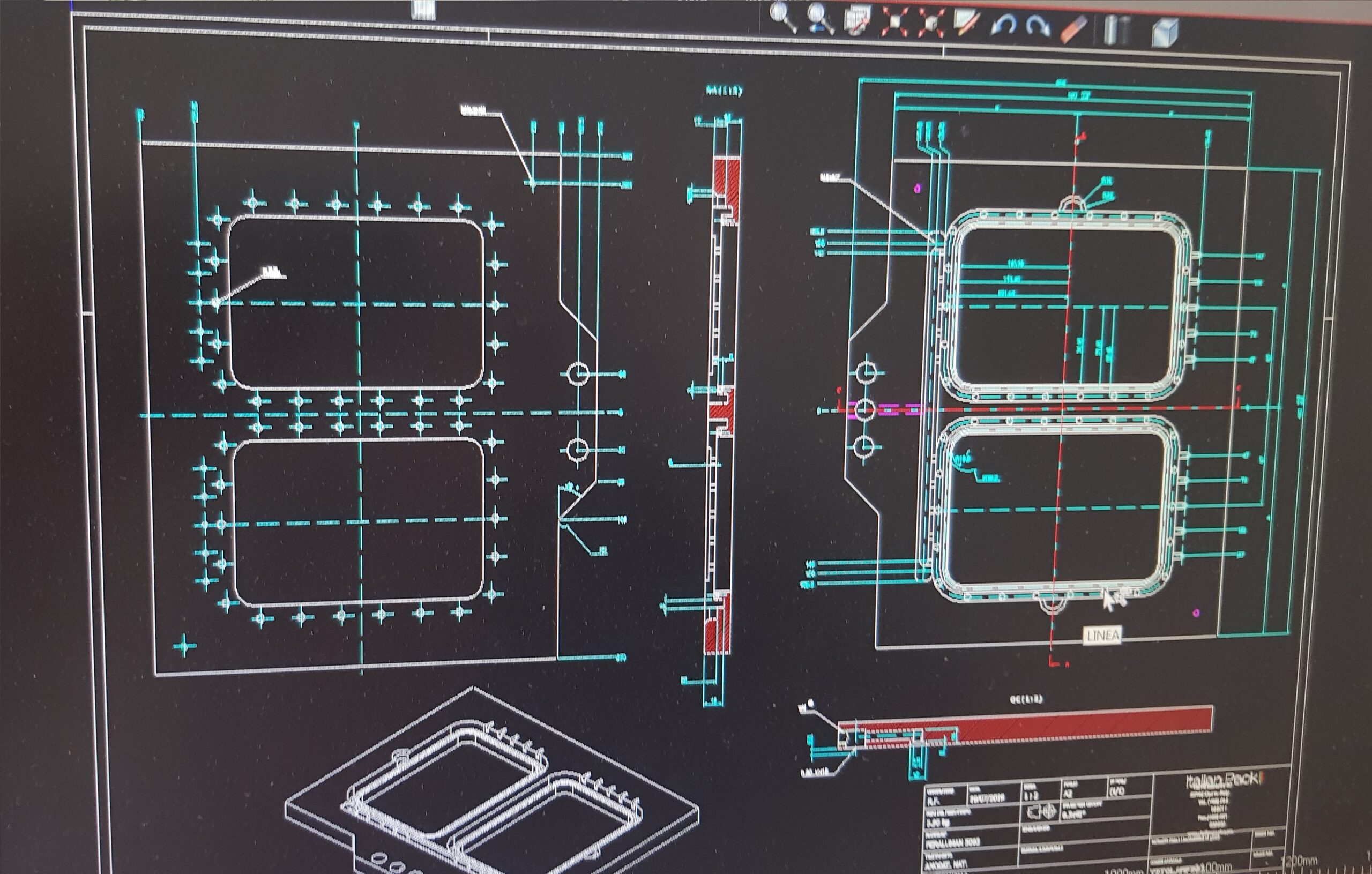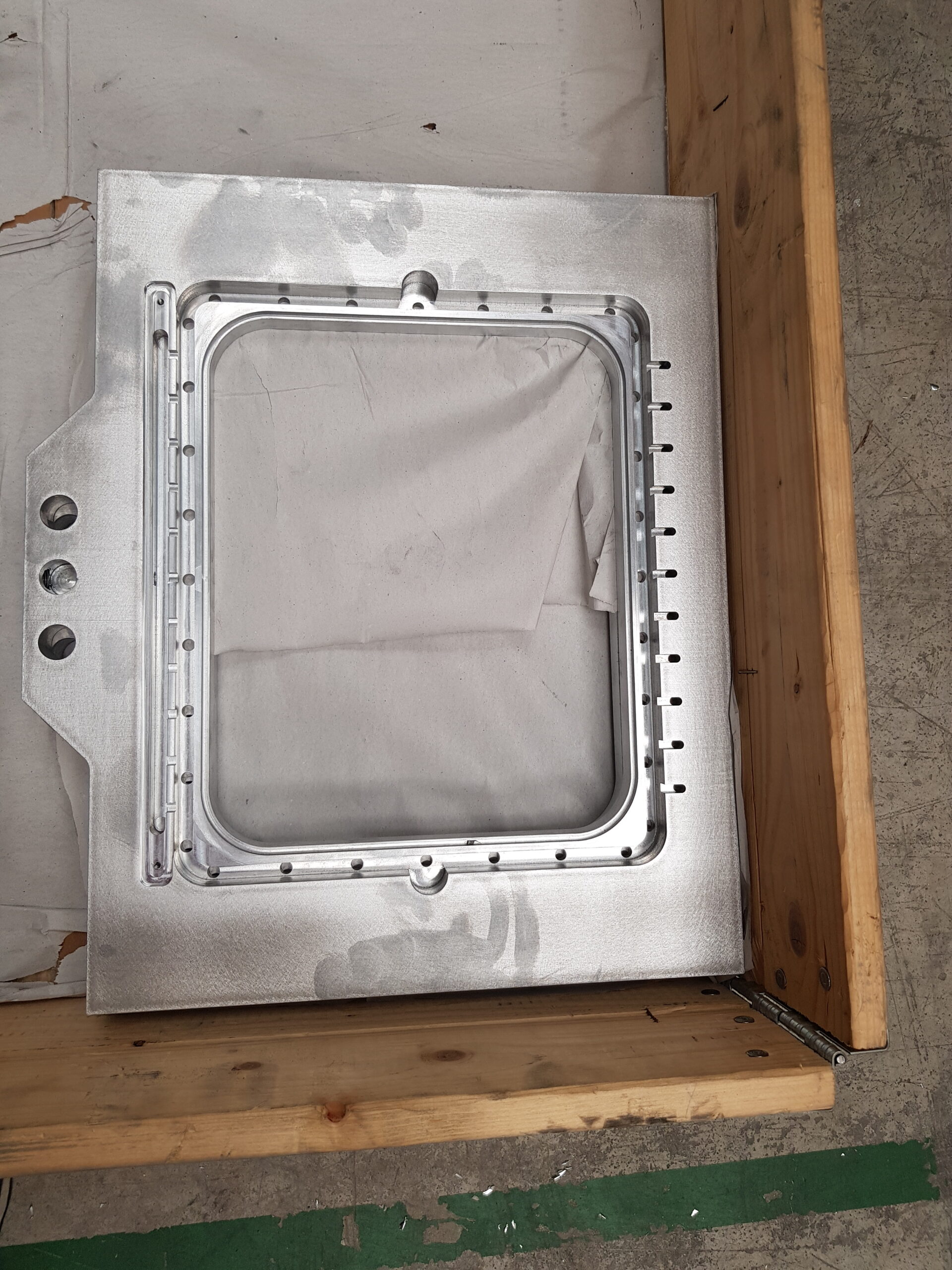
IDMCAD CAM MEC is the software of the IDMCAD family dedicated to manufacturing companies that operate in the MECHANICS sector and need to translate DWG drawings in ISO format for the numerical control machine.
It includes a series of specific commands for defining the design, geometry and technology to be used.
The operational sequences are as follows:
- Drawing of the workpiece in AUTOCAD: a few AutoCAD commands and some conventions are used to represent the workpiece.
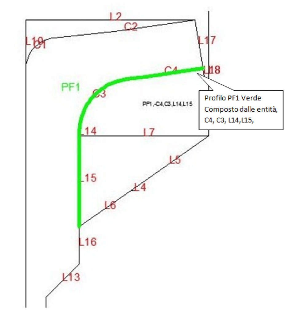
- Geometry definition: this function divides the entities drawn at intersection points and labels them.
- Creation of work profiles: with this command the entities to be concatenated to have a profile to be machined are selected
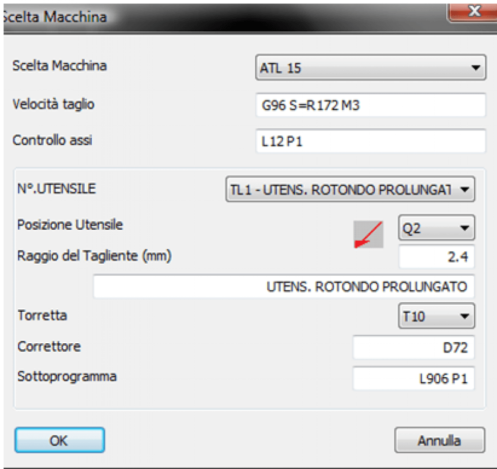
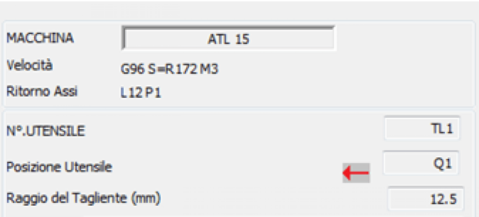
- Choice of the MACHINE and of the working TOOLS: the command activates the mask that allows the selection of the machine and the choice of the associated tool. This function selects a machine from the machine archive and a tool from the machine’s tool library.
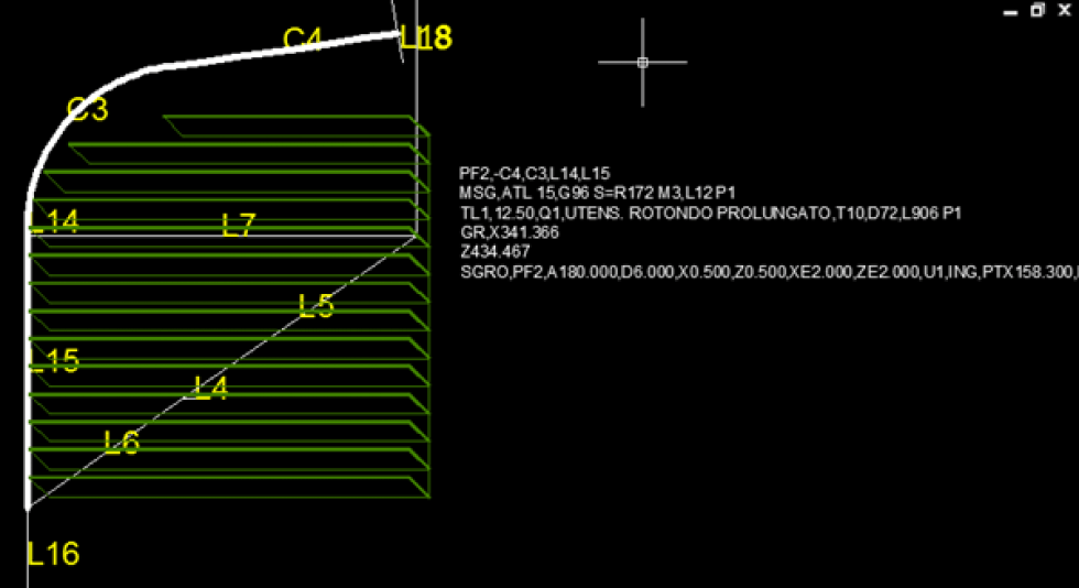
- Processing insertion: the user can insert ROUGHING, FINISHING AND POCK processing
- Insertion of manual commands: with this command it is possible to insert the operative sequences of work GL or rapid GR in every point of the descriptive list of the workings
- Path simulation: the simulation takes place by selecting the path and represents the movement of the tool taking into account the radius and the translated tool. The simulation is done on the final ISO path
- CAM Extraction: Extracting the ISO for the selected machine. The program rereads the list of operations and converts them into machine language. Depending on the post processor the output can go to different machines.

